For years I’ve been running my home automation switchboards using “temporary” controllers using Ethernet-enabled Arduino boards controlling DIN-rail mounted relays. My hope was that some day, someone would release a DIN-rail mounted control system with wired connectivity.
And now, all these years later, Allterco have done it. The new Shelly Pro 4PM looks like exactly the device I’ve been waiting for.
Disclosure: Allterco sent me this pre-release unit free of charge. However, I have personally paid for Shellys in the past and I’m sure I will in future. They had no input into this video, which is my own honest assessment of the Pro 4PM.
The Shelly Pro 4PM supports MQTT control out of the box. All you need to go is go into the MQTT configuration menu, put in the details for your broker, and it will be ready to go.
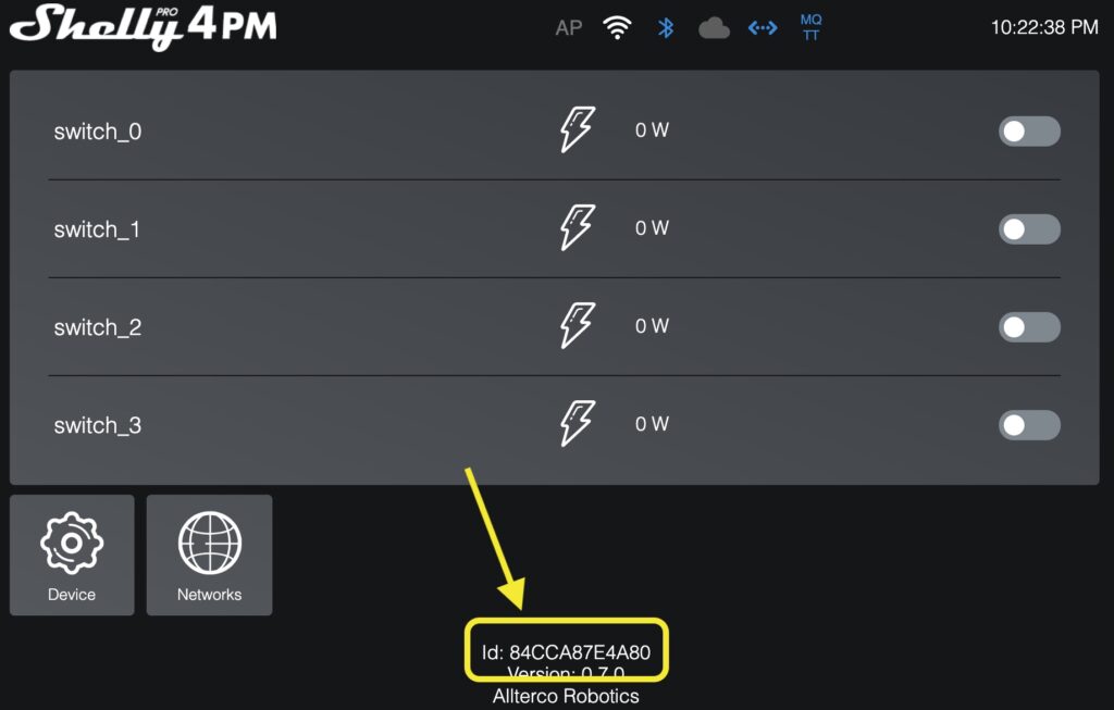
The MQTT topics are based on the device ID of the specific Shelly module, but converted to lower case. You can find the ID by opening the web interface and looking at the bottom:
The topic for sending commands to the Shelly is of the form:
shellypro4pm-<device_id>/rpc
So based on the device ID in the screenshot above, you can see the command topic would be:
shellypro4pm-84cca87e4a80/rpc
Messages are sent and received as JSON. To turn on an output, send a message to the command topic of the form:
This example turns on the first channel, because in the “params” section it has the ID set to 0 and the “on” value set to “true”. To turn off the first channel, change the “on” value to “false”.
Turn control the second channel, use the id “1”, and so on.
To see events published by the Shelly, including when channels change state and how much power each device is using, subscribe to the topic of the form:
Part 3: Tasmota conversion using a direct serial connection
Part 4: Replacing a Tuya module with an ESP8266
The easiest and safest way to convert a Tuya device to Tasmota is using Tuya-Convert.
This clever utility uses a security loophole to trick your Tuya device into thinking that it’s installing an updated version of itself, when in fact it’s replacing itself with Tasmota. This means you can do the conversion without any electrical connection to the device: you don’t need a serial connection, and you don’t need to open the case.
This is great because there’s no risk of electrocution and it can be safely done by anyone.
To use Tuya-Convert, three things need to be true:
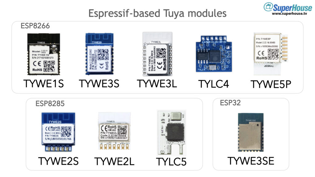
Your Tuya device must use a module based on an Espressif ESP8266 / ESP8285 processor. This includes the TYWE1S, TYWE2S, TYWE2L, TYWE3S, TYWE3L, TYLC4, TYLC5, and TYWE5P modules. There is also an ESP32-based module called the TYWE3SE but I don’t think it can be converted with Tuya-Convert.
The device must not have been updated to new Tuya firmware that closes the security hole required for Tuya-Convert to work. If you have a device you want to convert, do not allow it to connect to your WiFi or pair with the app before you do the conversion. That may cause it to do an update and lock you out.
You must be able to put the device into “EZ Mode” manually. Usually this is done by holding down the primary power button for 5 seconds, but it can vary between devices. For devices like smart lights that don’t have a power button, it can sometimes be done by turning its power on, off, on, off, on and then waiting a few seconds.
If your device doesn’t meet these requirements, you can’t use Tuya-Convert and the rest of this tutorial isn’t any use to you. However, you may still be able to convert it using one of the other methods that I’ll show in the next two videos.
Sometimes manufacturers change from one type of Tuya module to another, without making any external changes to their product or the packaging. You can buy a device one day and it has an ESP8266-based Tuya module in it, and buy the same product a week later only to find it now has a Realtek-based Tuya module instead.
To be absolutely sure, you can open the product and check if the module is one of the ESP8266 or ESP8285 versions:
“EZ Mode” is one of the two possible methods that Tuya provide for pairing a device with their app and connecting it to your home network.
With EZ Mode, the device broadcasts a message asking if there is an existing network that it can connect to. Tuya-Convert listens for this broadcast and responds to it, allowing the device to connect to it.
The other mode is “AP Mode”, where the device starts its own WiFi network and then you need to connect to its network to configure it. Tuya-Convert doesn’t work with this mode.
You can run Tuya-Convert in a docker container or on a laptop or PC if you prefer, but for this tutorial I’m going to do a clean setup on a Raspberry Pi. This has the advantage that you can set up everything you need on an SD card, run your Pi while doing the conversion, and then take the SD card out and store it safely for future use.
Next time you want to convert a Tuya device, you can find a handy Raspberry Pi, pop in the SD card, power it up, and in about a minute you’re ready to go.
Install Raspberry Pi OS
Download the official Raspberry Pi Imager software on your Mac, PC, or Linux machine, insert your SD card, and install the default Raspberry Pi Desktop. The process is very simple and there are instructions on the Raspberry Pi site.
Once the SD card is ready, plug it into your Raspberry Pi, use the Ethernet cable to connect your Pi to your network, and turn it on.
Note that you must use a cabled Ethernet connection. You can’t use WiFi to connect your Pi to the Internet because it needs to use its onboard WiFi hardware to create a special network for the Tuya device.
With your Raspberry Pi running and connected to your Ethernet network, open the “Terminal” program directly on the Pi or connect to it by SSH.
Set WiFi region
Configure your geographic region in Raspberry Pi OS so that it will use the correct WiFi frequencies.
Launch Raspi-Config:
sudo raspi-config
Go through the menus to select “Localisation Options“, then “WLAN Country“, then choose your country. Select “OK”, then “OK” again, then “Finish”, and let your Pi reboot.
Once it has finished rebooting, log back in.
Update Raspberry Pi OS
Make sure the operating system is fully up to date:
sudo apt update
sudo apt dist-upgrade
Raspberry Pi OS usually includes Git pre-installed, but just to make sure you can run this command. It’s safe to run even if Git is already installed:
sudo apt install git
Set up Tuya-Convert
In your home directory, download the latest version of Tuya-Convert, change into its directory, and then run the provided script to install the prerequisites:
cd ~
git clone https://github.com/ct-Open-Source/tuya-convert
cd tuya-convert
sudo ./install_prereq.sh
Running the script will take a few minutes. Once it has finished, your Pi will be fully set up to run Tuya-Convert. You don’t need to do any of the previous steps again. Each time you boot up your Pi, it will be ready to go.
Prepare for conversion
With all the software already installed by the previous steps, start Tuya-Convert on your Pi. If you’ve just completed the installation steps above, you will already be in the “tuya-convert” directory. This pair of commands makes sure you’re in the correct directory in case you set up your Pi previously and have logged in again:
cd ~/tuya-convert
sudo ./start_flash.sh
Tuya-Convert gives you step by step instructions as it runs.
It will start by asking you whether it should terminate dnsmasq and mosquitto. Say yes (“y”) to both questions.
Next it will come to a screen with 3 steps listed. At this point you need to have your phone or tablet handy.
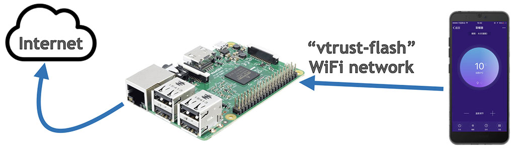
When Tuya-Convert starts, it creates a WiFi network called “vtrust-flash”. Use your mobile phone or tablet to connect to this network, and use the password “flashmeifyoucan“.
Because the network doesn’t have Internet access, your phone or tablet may complain and say that it wants to switch back to your normal WiFi network. If necessary, tell it to stay on the vtrust-flash network.
Your setup should now look like this, with your Pi connected to the Internet via Ethernet and your phone or tablet connected to the Pi via WiFi:
Put your phone or tablet aside. It doesn’t do anything for the rest of the process: it’s only there so that there is always at least 1 device connected to the vtrust-flash network, to keep it active.
Your Pi should still be waiting patiently with the 3 steps listed in the terminal, and it’s now ready to convert as many devices as you want.
Run conversion
Plug in your Tuya device, and then put it into EZ Mode. Usually this is done by pressing the main “power” button on the device for at least 5 seconds, but some devices require you to turn its power on, off, on, off, on and then waiting a few seconds.
If your Tuya device has a status LED, it will then start flashing to indicate that it’s in EZ Mode.
In the terminal on the Pi, press ENTER to tell Tuya-Convert that you’re ready to proceed.
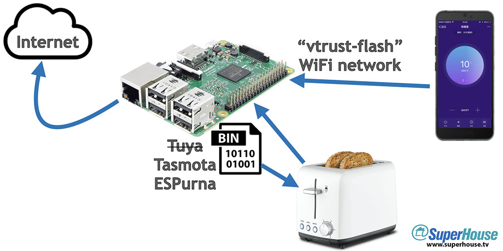
Tuya-Convert will then pair with your Tuya device, and take a backup of the existing firmware. It saves this backup on your Pi and you can use it later if you want to restore your Tuya device to its original factory setup, but don’t rely on that! After this point it’s best to assume that your device is never going back to its original setup.
You’re now faced with a list of options. The terminal will say:
Available options:
 0) return to stock
 1) flash espurna.bin
 2) flash tasmota.bin
 q) quit; do nothing
Please select 0-2:
You can bail out at this point by typing “q”, and your device will be left untouched.
This is the point of no return! To install Tasmota, press 2.
After all the setup that you’ve already done, actually flashing Tasmota to the Tuya device only takes about 9 seconds.
Congratulations! Your Tuya device now has Tasmota installed.
Tuya-Convert will now ask if you want to convert any more devices.
If you only had one device to convert, you can say “N” (or just press ENTER) and Tuya-Convert will exit. You’re now ready to follow the normal Tasmota setup and configure your device.
If you have more devices to convert, you can unplug the device you just converted, plug in your next device, put it into EZ Mode, and select “y” in the terminal. Repeat this cycle as many times as you like to convert all your devices.
Once you’ve finished converting devices, don’t forget to switch your phone or tablet back to your normal WiFi.
If you think you may want to convert more Tuya devices in future, shut down the Pi cleanly and then put the SD card aside. This saves you going through the long setup process of installing Raspberry Pi OS, Tuya-Convert, and all the required software. It will be ready to go next time you need it.
I keep my collection of SD cards in small envelopes, with the purpose of the SD card (including the username and password) written on the envelope. That saves me trying to remember what’s on each of my SD cards, or how to log into them.
Configure Tasmota on your device
Tuya-Convert installs a very basic Tasmota binary that will allow your device to connect to WiFi, but it may not be the specific Tasmota build that your device requires for its features to work.
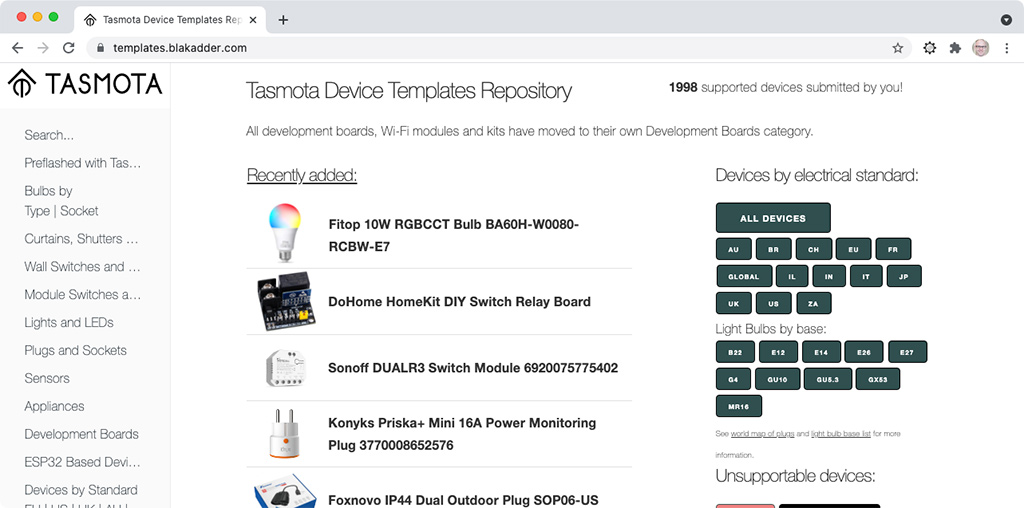
The best place to get information about specific devices is the Tasmota Device Templates Repository. Look up your device there to find out what Tasmota build you need to install, and how it should be configured.
Finally, if you’ve found Tuya-Convert to be useful, please consider supporting the project by making a small financial contribution. Links for that can be found on the Tuya-Convert page.
Part 3: Tasmota conversion using a direct serial connection
Part 4: Replacing a Tuya module with an ESP8266
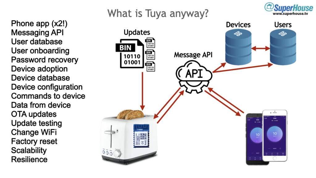
Tuya is an important part of the DIY home automation ecosystem, but it’s easy to underestimate everything that it can do. In Part 1 of this mini-series I explain what Tuya is, and why it’s so attractive to appliance manufacturers. Why don’t they all just make their own apps and IoT infrastructure? There’s more to it than you may realise!
Device manufacturers could build their own IoT platform from scratch, but it’s a huge job. There are many pieces to the puzzle, and you can’t just build it once and then leave it. You have to commit to 24/7/365 operation, with round the clock staff to make sure your system always works.
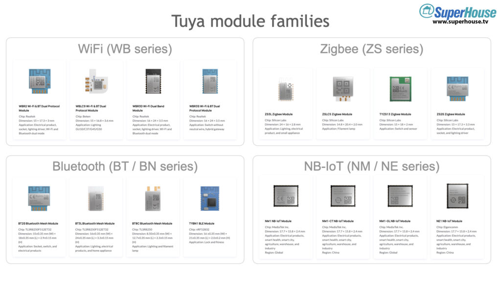
Tuya makes a range of modules to suit different purposes, grouped into families based on the radio type. They have families for:
WiFi
Bluetooth
Zigbee
Narrow band IoT
LTE-4G
Each family has multiple modules with different physical shapes and I/O options, so that manufacturers can select the one that best suits their needs.
The names of the module families indicate the radio type included on the module, and the manufacturer of the microcontroller that’s included. For example, the “WBR” series supports WiFi (“W”) and Bluetooth (“B”) and has a Realtek (“R”) microcontroller onboard. Once you understand the naming convention, you can look at a Tuya module and have a good idea of what it can do.
Tuya modules are available fully certified in many parts of the world, so they’re a great source of hardware that’s officially approved for use. However, the Tuya firmware ties devices to the rest of Tuya’s infrastructure, so hobbyists often replace the factory firmware with an Open Source replacement such as Tasmota.
But there’s a catch. Tasmota only runs on ESP8266, ESP8285, and ESP32 microcontrollers.
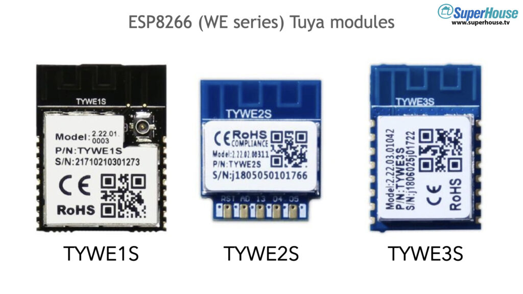
Early Tuya modules were based on the ESP8266/ESP8285 microcontroller, and had the family name “WE”. These included the TYWE1S, TYWE2S, and TYWE3S.
Both to save cost and to prevent their firmware from being replaced and keep users locked into their ecosystem, Tuya have moved away from Espressif microcontrollers. Many older products still ship with TYWExS modules because they were designed before the move to other microcontrollers, so if you can find products with these older modules then it makes things much easier for you.
In the next few videos I’m going to show you how to convert Tuya devices to run Tasmota.
Finally, if you’ve found Tasmota to be useful, please consider supporting the project by making a small financial contribution. Links for that can be found on Tasmota’s “Contributing” page.
There are far too many one-off programming headers for Espressif MCUs. I wanted a simple programming header that I could use consistently across my projects, and I was surprised that there hasn’t been any consensus around a single header.
This is my attempt to specify a header format that can be used in future ESP8266 / ESP32 projects, and hopefully could even be adopted by companies that make popular products based on Espressif chips.
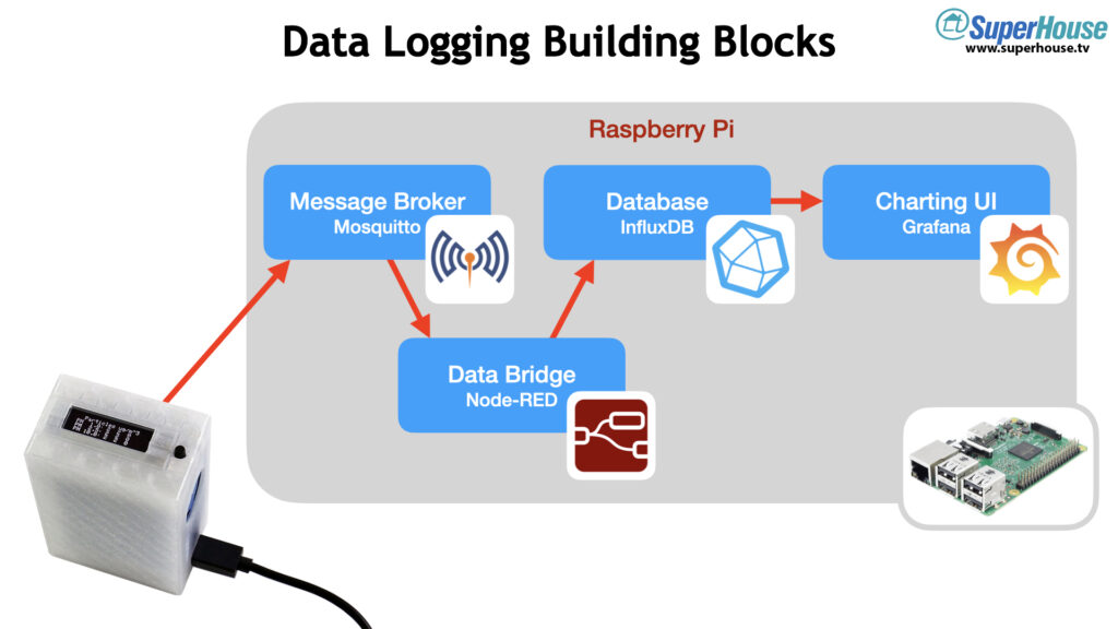
Whatever data source you want to record, there are a few common building blocks that you will need. Each of these building blocks has multiple alternatives. There are also totally different architectures that do things in a different way.
However, this particular combination of software is ideal for home automation, because these software building blocks can also be used for other purposes within your overall system.
You can install the various software elements on different computers, or in virtual machines, or using Docker containers, or on a NAS, or in many other ways.
To keep it simple and because many people already have one spare, we’re going to use a Raspberry Pi.
Prepare Raspberry Pi
Begin by installing Raspberry Pi OS (formerly known as “Raspbian”) on your Raspberry Pi. The easiest way to do it these days is to use the Raspberry Pi Imager, which runs on Windows, MacOS, or Linux and can be downloaded from www.raspberrypi.org/downloads/.
Use the Imager to download and install Raspberry Pi OS onto a micro SD card, insert it into your Pi, and start it up.
TODO: logging in first time.
Make sure your Pi has the latest packages by applying all updates:
sudo apt update
sudo apt upgrade
You now have a Raspberry Pi with a basic Raspbian OS installation, ready for customisation.
Step 0: Get the IP address
We’ll need to know the IP address of the Raspberry Pi later. If you’ve connected using the hostname or you’re using a screen and keyboard, you can get the
Step 1: Install the Mosquitto MQTT broker and clients
There are many different MQTT brokers available, but Mosquitto is the most popular and it has served me well for many years. Install both the “mosquitto” package and the “mosquitto-clients” package, so that you have both the broker and some handy command line clients that you can use for testing:
sudo apt install mosquitto mosquitto-clients
The Mosquitto broker will be set up with a default configuration and will work fine out of the box, but we’re going to change the configuration to make it more secure.
You can leave your MQTT broker unprotected, but it’s a good idea to set a username and password on it.
First, create a text file that contains the username and password with a colon to separate them. You can do this on the command line with a single command:
echo "mqtt_username:mqtt_password" > pwfile
This will create a text file called “pwfile” with the details in them.
Use the passwd utility provided as part of the Mosquitto package to encrypt the file:
mosquitto_passwd -U pwfile
Display the contents of the file to verify that it has now been encrypted:
cat pwfile
You will see your username in plaintext, followed by a string of gibberish which is the encrypted form of the password. If the password is still plaintext, it means the encryption command above didn’t work.
Move the encrypted file into the Mosquitto configuration directory:
sudo mv pwfile /etc/mosquitto/
Mosquitto needs to be told where the new file is located. Use an editor such as Nano to open the Mosquitto configuration file:
sudo nano /etc/mosquitto/mosquitto.conf
Near the bottom of the file, just above the “include_dir” line, add these lines:
The first line tells Mosquitto to reject all anonymous connections, and require a password.
The second line tells Mosquitto where to find the list of allowed usernames and passwords.
To save your changes and exit, type CTRL+X, then Y, then ENTER.
Restart Mosquitto so that it uses the new configuration:
sudo /etc/init.d/mosquitto restart
From now on, all connections to your MQTT broker will need to supply the username and password that you configured.
Step 2: Install the InfluxDB time-series database
To install InfluxDB we can use its official repository, because the developers have provided a packages specifically for different operating systems on the Raspberry Pi.
Start by fetching the official repository key and adding it to the local keyring:
Now you can add the repository. There are a few different versions available, so you need to copy and paste the command that matches your operating system.
To find out what version you’re running, you can type the following command:
lsb_release -a
This is will report the operating system type and version, usually with a codename like “Stretch” or “Buster”. Copy and paste the command that matches your system.
For Raspbian Stretch:
echo "deb https://repos.influxdata.com/debian stretch stable" | sudo tee /etc/apt/sources.list.d/influxdb.list
For Raspbian Buster:
echo "deb https://repos.influxdata.com/debian buster stable" | sudo tee /etc/apt/sources.list.d/influxdb.list
For Ubuntu 20.04LTS:
echo "deb https://repos.influxdata.com/ubuntu focal stable" | sudo tee /etc/apt/sources.list.d/influxdb.list
For Ubuntu 18.04LTS:
echo "deb https://repos.influxdata.com/ubuntu bionic stable" | sudo tee /etc/apt/sources.list.d/influxdb.list
Now that the repository has been added, we need to update the list of packages that are available:
sudo apt update
Install the database package:
sudo apt install influxdb
Tell the systemctl service manager to enable InfluxDB at startup:
Start InfluxDB manually this time. In future, it will be started automatically whenever your Raspberry Pi boots up:
sudo systemctl start influxdb
Let’s set up access control for InfluxDB before we do anything else. The default installation of InfluxDB leaves the system wide open, so we’ll start by creating an admin user and setting a password.
Connect to InfluxDB by running the client. We don’t need to use a username or password this time, because nothing has been set yet:
influx
Create a user called “admin”, and put in the password you want to use for it:
CREATE USER admin WITH PASSWORD 'adminpassword' WITH ALL PRIVILEGES
Now you can exit out of InfluxDB. Simply type “exit” and press ENTER.
exit
The InfluxDB configuration needs to be edited so that it will use authentication. Otherwise the admin user that we just created will be ignored. Use a text editor to open the InfluxDB config file:
sudo nano /etc/influxdb/influxdb.conf
Press CTRL+W to search for the section called [HTTP].
To save your changes and exit, type CTRL+X, then Y, then ENTER.
The config change won’t be applied until InfluxDB has been restarted, so restart it manually:
sudo systemctl restart influxdb
From now on, any time you want to connect to the InfluxDB command line you will need to supply the username and password.
We need to do that now, so substitute the password you set:
influx -username admin -password <adminpassword>
If the previous changes worked, you should now be connected to InfluxDB again and authenticated as the admin user that you just created.
Next we need to tell InfluxDB to create a database where we can store sensor data. In this example I’ve simply called the database “sensors”:
CREATE DATABASE sensors
That was easy! Because of the way InfluxDB works, there’s no need to create a schema with tables and columns like you would be a relational database such as MariaDB, MySQL, Postgres, or SQL Server.
All you need to do is create an empty database, and it will be automatically populated when you start sending data to it.
Leave the InfluxDB client by typing exit, as before:
exit
Step 3: Install Node-RED
There are several different ways to install Node-RED, and it’s readily available in the Raspbery OS packaging system. However, the Node-RED team recommend that you do NOT use the packaged version.
Instead, they provide a handy script that installs the latest version of Node-RED from the official release, and helps you keep it updated. The installation script goes far beyond that, however. It also:
makes sure there’s no existing installation of Node-RED and removes any that it finds in order to prevent conflicts
installs the latest Node.js
gives you the option of installing a set of useful nodes specifically designed to run on a Pi
sets up Node-RED to run as a service and installs tools to help you manage it
Before running the Node-RED installation script, install the tools needed by NPM to build binary modules:
sudo apt install build-essential git
Now you can run the official Node-RED installation script:
The script will ask you a couple of questions about whether you are sure you want to proceed, and whether to install Pi-specific nodes. Say “y” (yes) to both questions.
Node-RED can be extended by installing modules to give it extra features. We need to do that now so that it can connect to your InfluxDB database. Use NPM to install the InfluxDB nodes:
npm install node-red-contrib-influxdb
At this point Node-RED is be installed, but just like with InfluxDB you need to configure it to be automatically started on boot:
sudo systemctl enable nodered.service
You can start the service manually this time, but in future it will happen automatically when your Pi starts up:
sudo systemctl start nodered.service
Step 4: Install Grafana
Just like with InfluxDB, we can install Grafana by adding the official repository and installing the package. Start by fetching the public key for the repository and adding it to the local keyring:
echo "deb https://packages.grafana.com/oss/deb stable main" | sudo tee -a /etc/apt/sources.list.d/grafana.list
Update the package list (again!) and install the Grafana package:
sudo apt update
sudo apt install grafana
Just like the other packages we’ve installed, we need to enable the service so that it will start automatically:
sudo systemctl enable grafana-server
That takes care of starting Grafana at boot. For now, let’s start it manually:
sudo systemctl start grafana-server
Step 5: Configure your sensors to send data to MQTT
For each sensor that you want to log and report, you will need to go through a series of steps to ensure that the data is received by your Raspberry Pi, processed by Node-RED, stored in InfluxDB, and then charted using Grafana. This is a process that you will repeat multiple times as your build up your home automation system.
Let’s break it down into a series of simple steps.
Begin watching MQTT for messages. There won’t be any messages yet, but this is a handy technique for discovering new devices when they begin reporting to MQTT. On your Raspberry Pi, open a terminal and run the Mosquitto client command that we ran earlier:
This launches the Mosquitto client in “verbose” mode (the “-v” flag) and subscribes to all topics using the wildcard character. What this means is the client will display every message that is published by any client to any topic, and report not just the message but also the topic that it appeared in.
On a busy MQTT broker this is like drinking from a fire-hose!
However, we don’t have any sensors using our MQTT broker yet so you shouldn’t see anything happen: the terminal will just sit there waiting to display messages. Leave the terminal open so that you can see any messages that are published.
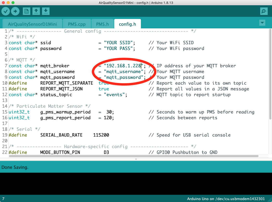
Configure sensor to report using MQTT. The exact process for this will depend on your device. Typically you will need to configure three things in your sensor:
The IP address (or hostname) of your MQTT broker. In this case, it’s the IP address of the Raspberry Pi.
The username and password for MQTT. We configured this way back at the start of the process. If you don’t have a username and password on your broker, you can skip this.
The MQTT topics for reporting. In many devices this should default to something sensible, and you may not need to change it. For our Air Quality Sensor project, the topic will be generated automatically based on the chip ID of the ESP chip.
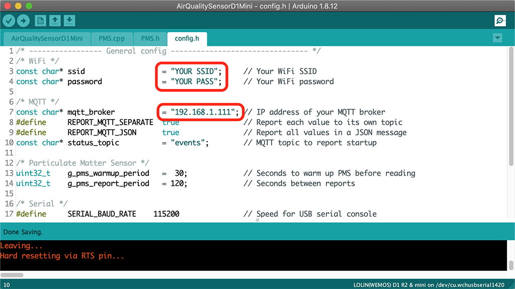
If you are using the example Arduino sketch for the Air Quality Sensor, open it in the Arduino IDE and go to the tab called “config.h”. Edit the broker IP address and the MQTT username / password to match your own settings:
Compile the sketch and flash it to the Air Quality Sensor, just like in the previous episodes.
After the sensor starts up with the new settings, you should see some action in the Mosquitto client! You’ll see a startup message from the sensor, and then it will periodically begin publishing its readings.
Step 6: Receiving and storing single-value sensor readings
aoeu
Step 7: Receiving and storing JSON-formatted sensor readings
aoeu
Step 8: Create a dashboard and widgets in Grafana
You can access the Grafana user interface using a web browser, by connecting to port 3000 on your Raspberry Pi. The URL will look something like:
http://192.168.1.248:3000
Substitute the IP address or hostname for your Raspberry Pi.
To log in, use the username and password “admin” and “admin”. Grafana will ask you to change the password on first login, so set it to something secure.
You can build the Air Quality Sensor project without understanding how the software works, but if you want to know what’s really going on behind the scenes you can join me for a deep dive into the source code.
It’s surprisingly easy to make your own simple air quality sensor. All you need is a cheap laser-scattering particulate matter sensor, a Wemos D1 Mini, a soldering iron, and Tasmota.
Part 1 showed how to make the simplest possible air quality sensor. Make sure you’ve seen that first, because Part 2 continues from Part 1 to add a 128×32 pixel OLED display and a mode button. We’re also going to install custom firmware to make the sensor last longer.
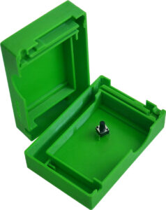
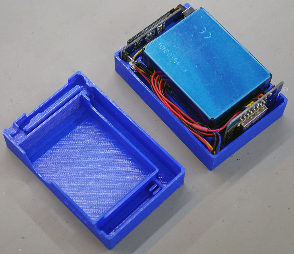
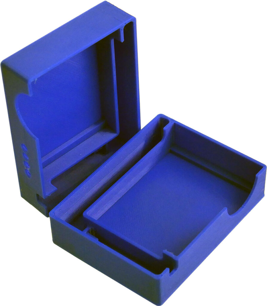
Printing a case is totally optional, of course. You can use whatever enclosure you like. My case has been designed to be a press-fit over the PMS5003, which holds the two halves together by friction. See the link above to download the STLs if you want to print it yourself, or you can buy a case from me if you don’t have access to a printer. I’ll include a 6x6x9mm tact switch with the “Display” version of the case:
Put switch into case
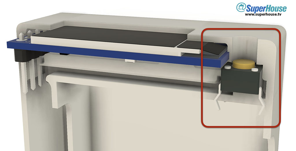
The space for the tact switch is very tight.
To fit it into the slot, trim off the pins from the right side and trim the pins on the left side so they are a couple of millimeters long. Bend those leads out at a 45 degree angle, and solder a pair of jumper wires to them.
Push the switch into the cavity in the case as shown above, and guide the wires around the slot to the left and then down.
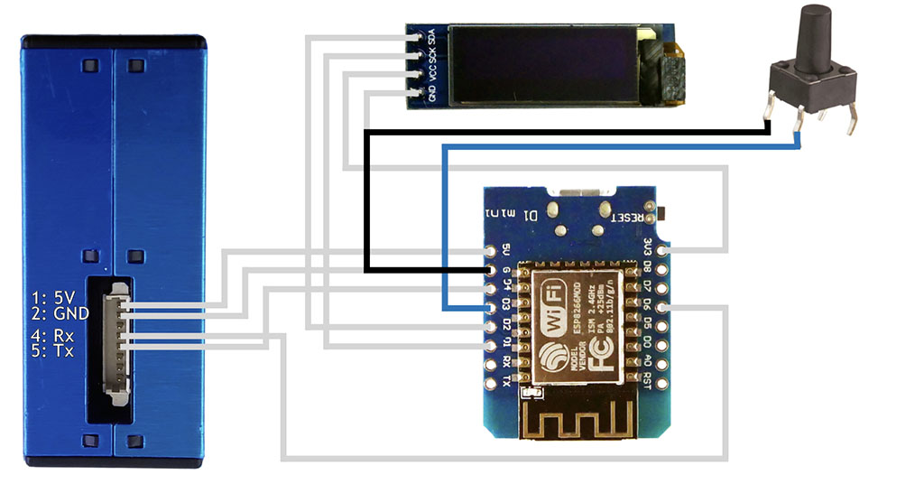
The button connects between GND and I/O pin D3:
Connect 128×32 OLED to D1 Mini
The 0.91″ 128×32 OLED module already has I2C pull-ups included, so there’s no need to add them. All we need to do is connect power and I2C:
The connections are:
OLED GND to D1 Mini GND
OLED VCC to D1 Mini 3.3V
OLED SCK to D1 Mini pin D1
OLED SDA to D1 Mini pin D2
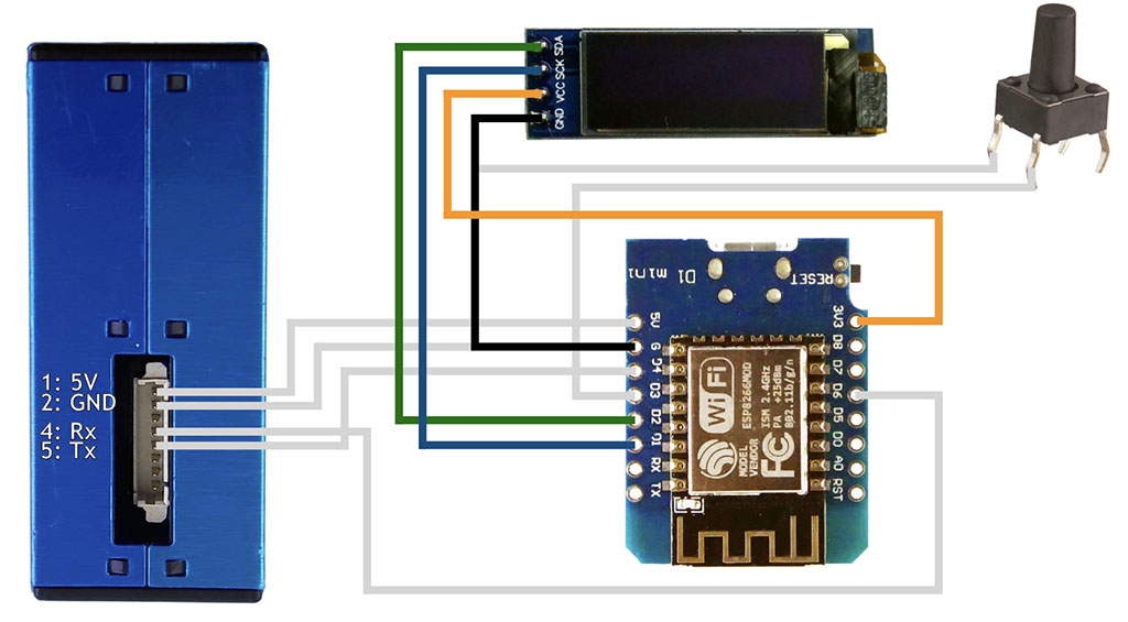
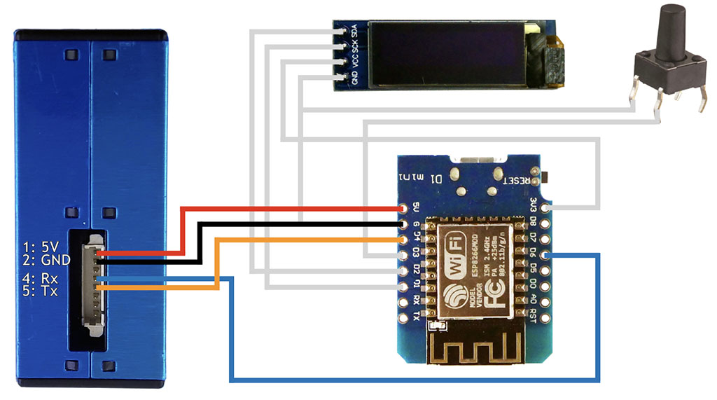
Connect PMS5003 to D1 Mini
In the “Basic” version of this project, we only needed to connect to the 5V, GND, and Tx pins of the PMS5003. Now we also need to connect I/O pin D6 to the sensor’s Rx pin, to allow commands to be sent to the sensor:
The connections are:
PMS5003 pin 1 (5V) to D1 Mini 5V
PMS5003 pin 2 (GND) to D1 Mini GND
PMS5003 pin 4 (Rx) to D1 Mini pin D6
PMS5003 pin 5 (Tx) to D1 Mini pin D4
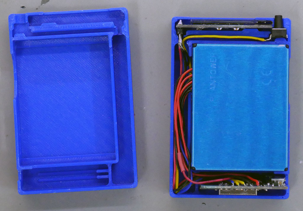
Close the case
This can be more tricky than it sounds! Be gentle so you don’t damage anything.
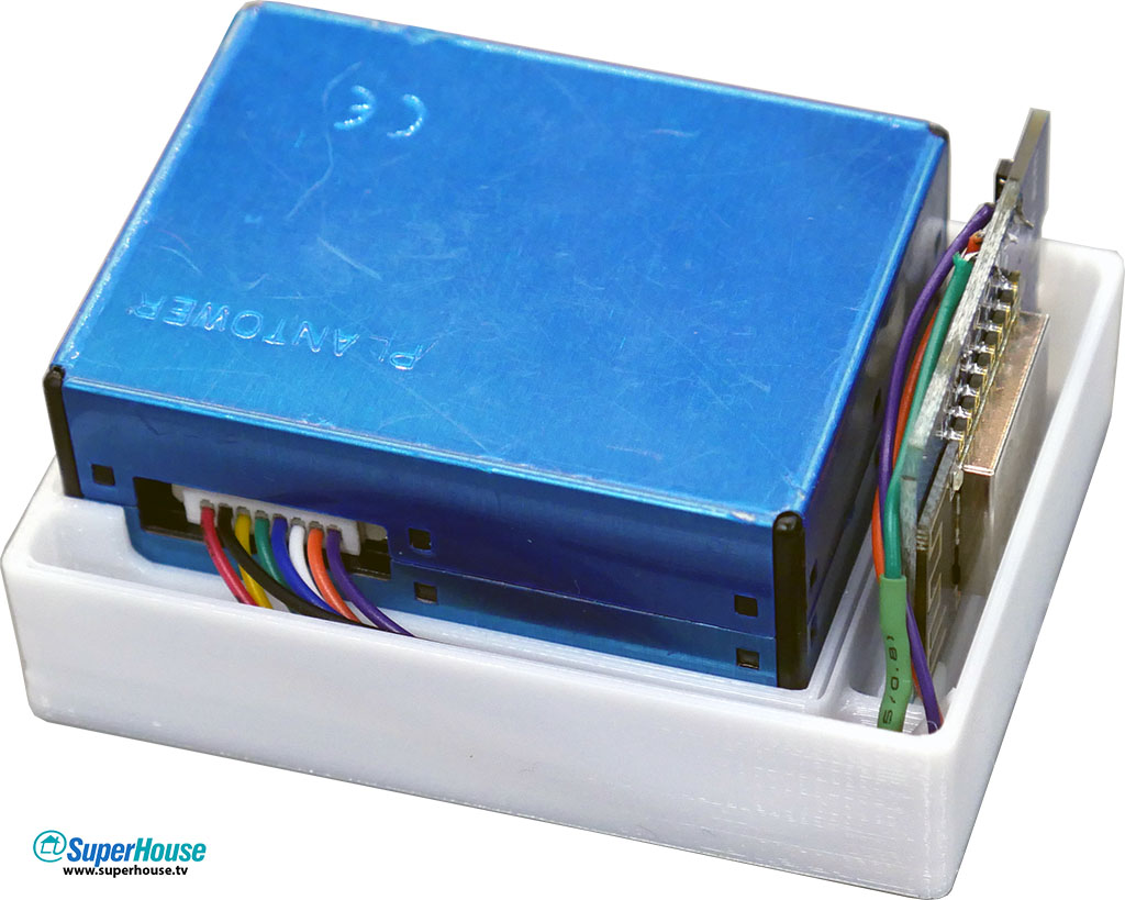
With the electronics sitting neatly in the “back” (or “right”) half of the case, make sure all the wiring is neatly tucked into the slots. It should look something like this:
Slide the other half of the case over the modules, checking that no wires are pinched between the halves. The case should close completely.
Set up Arduino IDE for ESP8266
If you don’t already have it, download and install the Arduino IDE:
By default, the Arduino IDE does not support the ESP8266 processor on the D1 Mini. To add this support, go to the following URL and follow the instructions. The easiest method is to use the Boards Manager:
The “PMS” library is directly embedded within the program, so you don’t need to install it. This is done to force a specific version of the library, which was forked from the official version by GitHub user SwapBap to add extra features. There’s nothing you need to do because it’s part of the project.
In the Arduino IDE, go into “Sketch -> Include Library -> Manage Libraries…“
Then search for each of these libraries, and click “Install”:
The easiest way is to click the green “Clone or download” button near the top right of the page and select “Download ZIP”. Once you’ve downloaded it, extract the folder and put it in your sketchbook directory. You can find the correct location for this by looking in the Arduino IDE preferences.
Configure and compile sketch
Open the Arduino IDE, open the sketch, and have a look at the 4 tabs across the top. You can ignore the first three. Open the “config.h” tab, and modify the settings for WiFi and your MQTT broker:
Plug in the Air Quality Sensor using a USB cable.
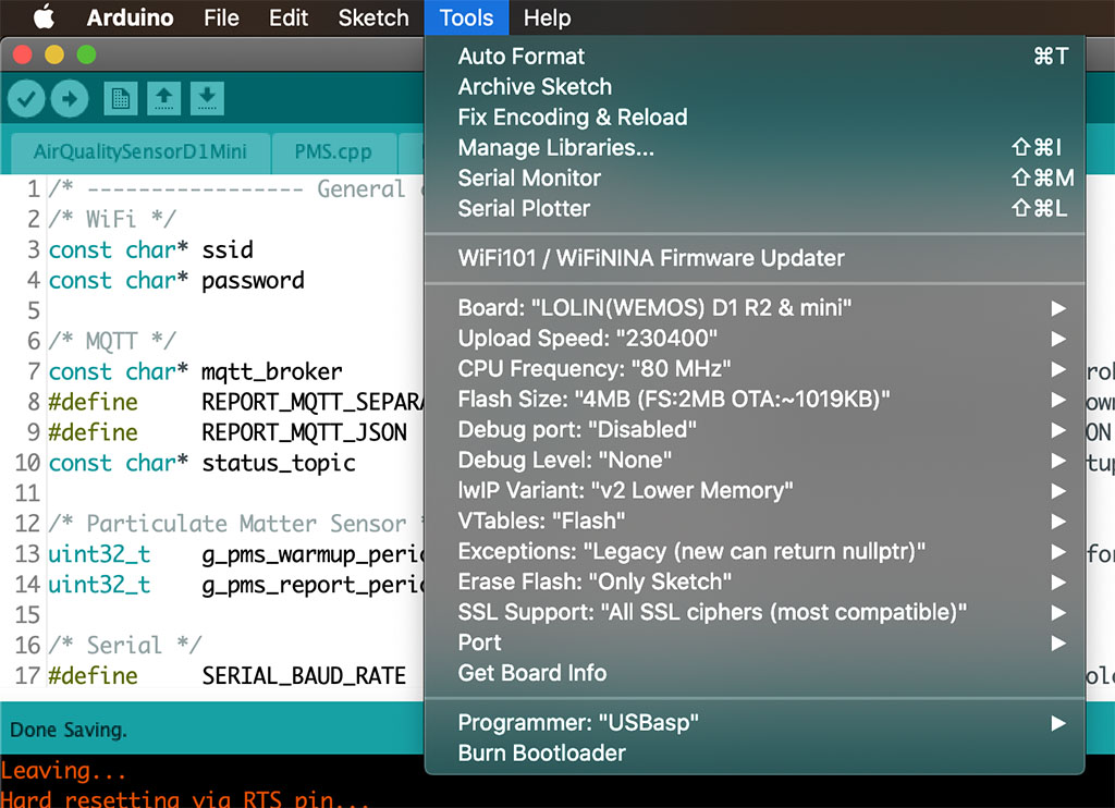
Select “Tools -> Board:” and set it to “LOLIN(WEMOS) D1 R2 & mini”. Select the port, and upload the sketch:
After the sketch has uploaded the Air Quality Sensor will reboot, connect to your WiFi and MQTT broker, and show values on the display once it has successfully received data from the PMS5003.
Stay tuned for part 3, which will explain how the sketch works and how to read the data from it.
It’s surprisingly easy to make your own simple air quality sensor. All you need is a cheap laser-scattering particulate matter sensor, a Wemos D1 Mini, a soldering iron, and Tasmota.
Part 1 shows how to make the simplest possible version of the SuperHouse Air Quality Sensor, the “Basic” version.
Part 2 shows how to improve it to make a more advanced “Display” version, Part 3 is a detailed walkthrough of how the firmware works, Part 4 will explain how various Air Quality Index calculations are done around the world, and Part 5 will step it right up with the “Pro” version with VOC sensor.
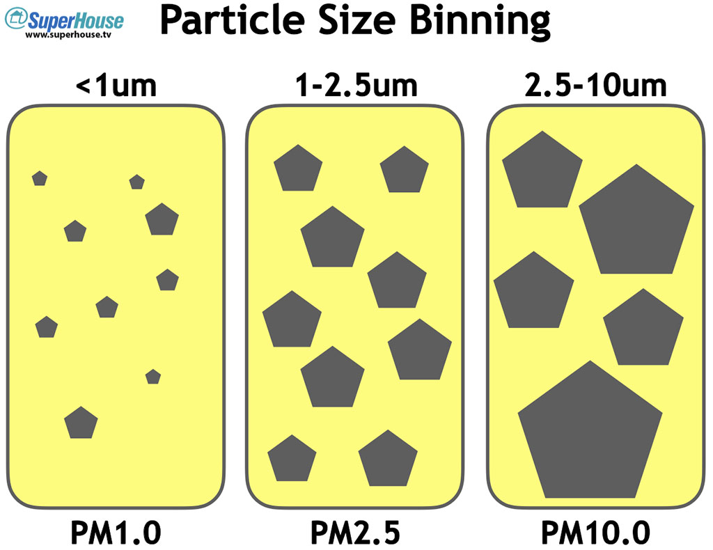
Here in Australia we’ve recently had a terrible bushfire season, and there’s been a lot of concern about the effects of smoke on air quality. Smoke particles, pollen, and many other forms of air pollution are tiny. Really tiny. Many people have been wearing “PM2.5” face masks, which means they are designed to filter out particles as small as 2.5 microns in size, but pollen and smoke can be even smaller than that.
Detecting tiny particles down in the 0.1 to 10 micron range is hard. Normally you’d need an electron microscope to detect something this small. In fact these particles are so small that they are often smaller than the wavelength of light, which is in the region of 0.5 microns. This means light doesn’t interact with them in the usual way: instead of bouncing off them like a particle, it can bend around them like a wave, and it can also refract inside them like tiny lenses.
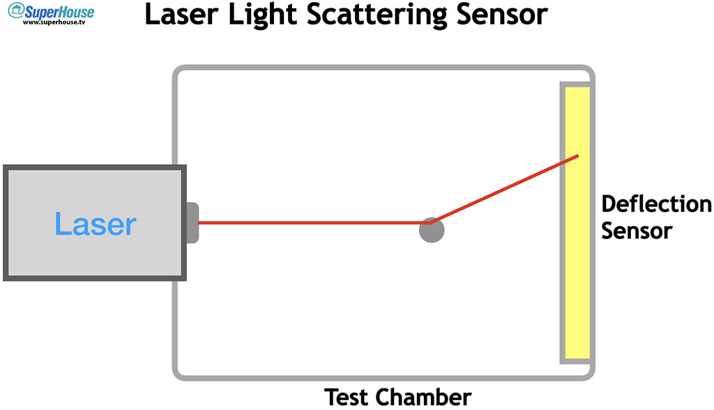
Laser-scattering particle detectors pass a laser through a test chamber, with a deflection sensor on the other side. Particles in the test chamber cause the beam to be scattered in different ways, and the deflection sensor can use this scattering to determine the number and size of particles in the chamber.
This process creates a series of concentric rings on the deflection sensor, which can use the spacing of the rings to determine the characteristics of the particles.
The particles that are detected are then categorised, or “binned”, into different size ranges for reporting.
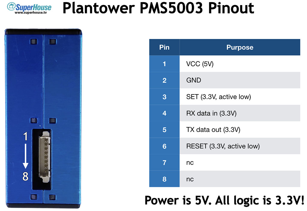
All of this functionality is wrapped up in the tiny Plantower PMS5003 sensor, which provides a serial interface to report the statistics for the particles that it detects.
Reporting is normally provided in a couple of forms.
The simplest number is the PPD value, which stands for “particles per deciliter”. The higher the number, the more particles there are in the air sample.
The most commonly used number is the “ug/m^3” value, which is micrograms per cubic meter. This is the total mass of particles in that size range in a cubic meter of air, so smaller particles will require a higher raw count to add up to the same mass as larger particles.
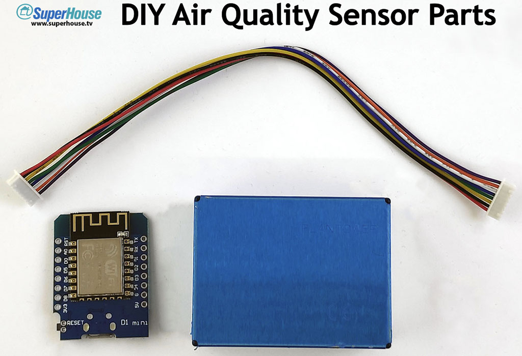
Parts required
The “Basic” version of the SuperHouse Air Quality Sensor only requires a a Plantower PMS5003, the connection cable that comes with it, and a Wemos D1 Mini. See the links above for sources to buy them.
You can also print your own 3D-printed enclosure, or buy one from me if you don’t have easy access to a printer.
Connect PMS5003 to D1 Mini
The PMS5003 requires a 5V supply because it has an internal fan to keep air flowing through the test chamber, but all its I/O connections are 3.3V.
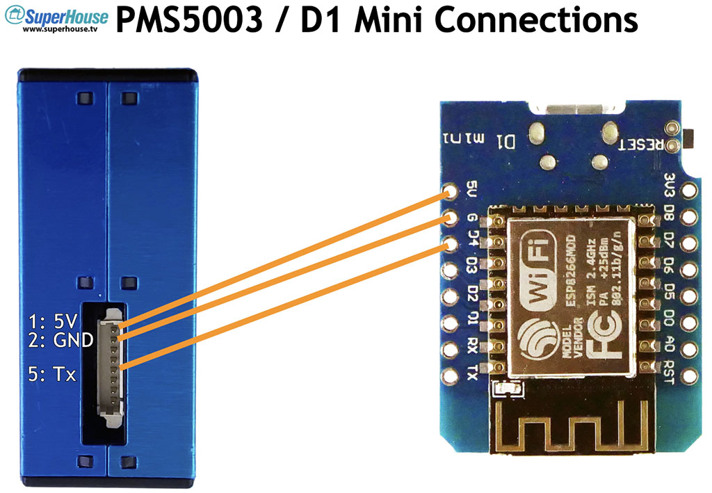
This is perfect for a D1 Mini, because we can connect the power pins to 5V on the D1 Mini and connect the sensor “TX” pin to an I/O header on the Mini.
Cut the supplied cable off at about 2/3rds of its length. Plug it into the PMS5003 to check the orientation, and then strip and tin the ends of the wires connected to pins 1, 2, and 5.
Connect VCC and GND from the PMS5003 to the 5V and GND headers on the D1 Mini.
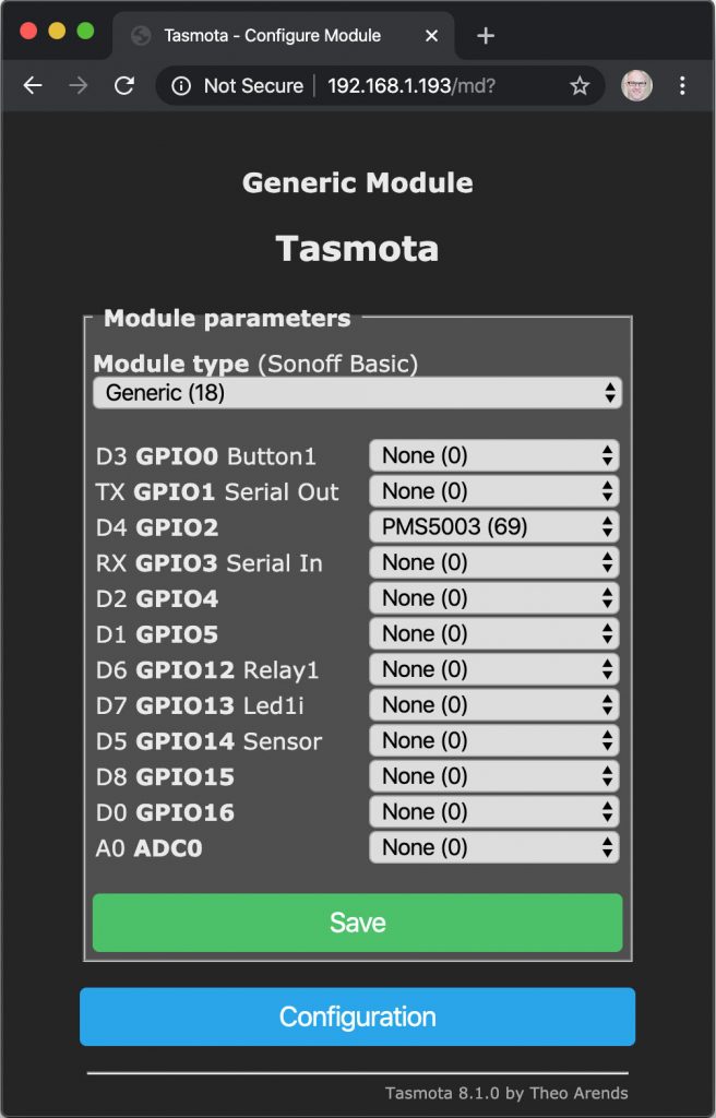
Connect TX from the PMS5003 to the D4 header on the D1 Mini, which is GPIO2 for the ESP8266 MCU.
3D printed case
I’ve designed a case that slips over the PMS5003 and provides a space for the D1 Mini and wires. You can download the STLs and print it yourself, or if you don’t have access to a 3D printer you can buy it from me in a variety of colour options.
The case comes in two halves. Insert the PMS5003 into the case first, and then slip the D1 Mini into the space at the bottom. The case is oriented so that if the USB socket is on the side towards the PMS5003 it will be accessible through a slot.
Push the wires down into the case so everything is neat, and then slide the other half of the case over the top. It may take some jiggling to get the wires out of the way and the D1 Mini properly inserted into the slot.
Install Tasmota
There are many ways to install Tasmota on the D1 Mini, but my new favorite is to use Tasmotizer. I did a whole video about how to install and use Tasmotizer, so follow the instructions here if you need to install it:
Once you have Tasmotizer running, connect the D1 Mini using a USB cable and select the port.
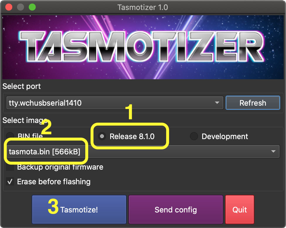
Note: As of Tasmota v8.2, support for the PMS5003 has been removed from the normal “tasmota.bin” release binary. Instead, you must select “tasmota-sensors.bin”.
Click the button next to “Release“.
From the drop-down, select “tasmota-sensors.bin” (not the regular “tasmota.bin” as shown above)
Click “Tasmotize!” and wait about a minute for the D1 Mini to be flashed and reboot.
Configure WiFi and apply the “SuperHouse AQS” template
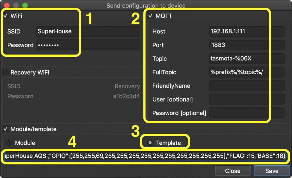
After the D1 Mini has been flashed, click “Send config” in Tasmotizer to open the configuration screen.
Click the checkbox to enable the WiFi section, and put in the details for your WiFi network.
If you use MQTT, click the checkbox to enable the WiFi section and put in the address for your broker. My personal preference is to change the “Topic” entry to “tasmota-%06X” so that the MQTT topics will be dynamically generated using the unique ID of each D1 Mini.
Click the button next to “Template”.
Copy the template below, and paste it into the text box at the bottom of the config screen:
Click “Save” to send the new configuration to the D1 Mini.
It will then restart, and will connect to your WiFi network using the values you just provided.
Connect to Tasmota web interface
You can use a serial console connected at 115200bps to get the IP address directly from the D1 Mini, or look in the management interface for your DHCP server to find the recently added device.
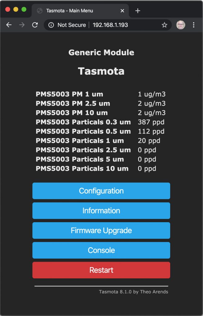
Once you’ve found the IP address, put it into a web browser to load up Tasmota’s web interface.
The module will report its latest readings, updating as fast as the sensor is sending them.
You can also configure the D1 Mini manually if you didn’t use the template above. Starting from a default Tasmota installation, log into the web interface and set up the module as shown below.
Access data via MQTT
Tasmota periodically publishes all the PMS5003 readings aggregated into a single JSON string, in the “../SENSOR” topic.
The topic will depend on the settings you applied for MQTT. In my case, with the “Topic” modified as explained above, the readings are published to a topic that looks similar to “tele/tasmota-5F596F/SENSOR” with the unique ID of this particular device substituted.
The published value will look something like this:
You can parse the JSON using your favorite method, such as with Node-RED. I’ll go over this in more detail in Part 2 when we look at more advanced software options.
The “PMx” values are micrograms per cubic meter. The “PBx” values are particles per deciliter.
Further improvements
This “Basic” version of the SuperHouse Air Quality Sensor is very simple to make, but it has a couple of limitations.
The laser and the deflection sensor in the PMS5003 can degrade over time. After about 6000 hours of continuous use it may begin to decrease in sensitivity. The life of the sensor can be dramatically extended by shutting it down for a couple of minutes, then waking it up, giving it time to stabilise, taking a reading, and shutting it down again. With this change the sensor can last for many years.
There is also no way to interact with the device directly. You have to access it over the network, either by loading the Tasmota web interface or by using the data published to MQTT. Adding a screen and a mode button can make it easy to read particulate levels directly on the device.
Both of these limitations are fixed in the “Display” version of the SuperHouse Air Quality Sensor in the next episode. Stay tuned!
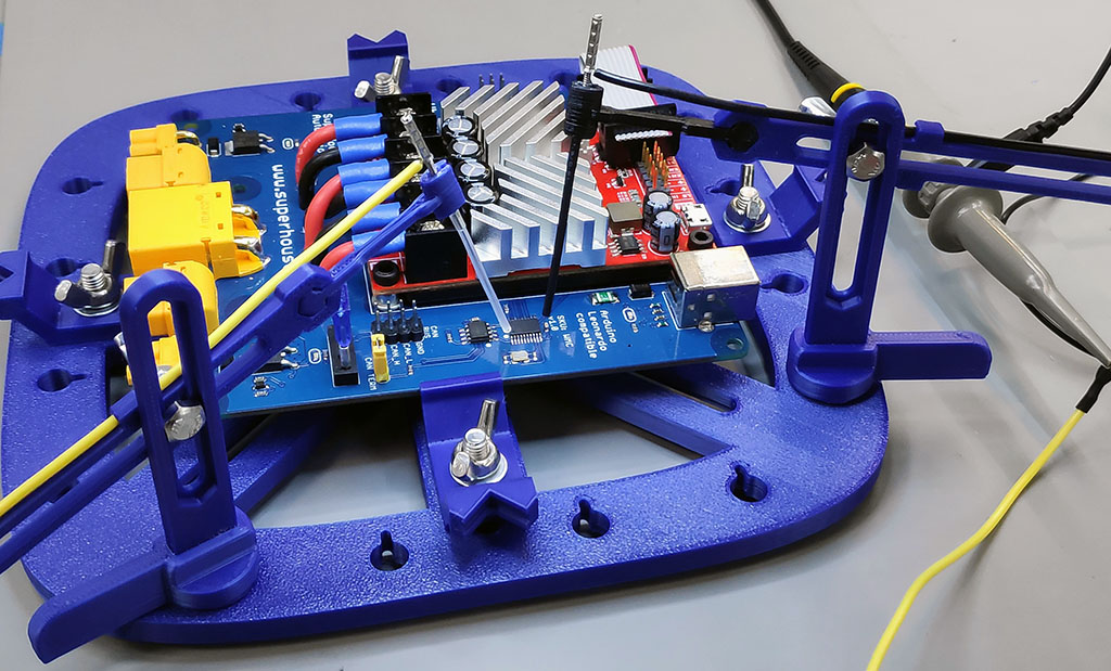
Connecting test probes to PCBs can be difficult when the contact points are very small, or when you need to keep the probes in place while using your hands to run tests or use a computer. Normal test probes for multimeters, oscilloscopes, and other equipment have to be held in place.
This amazing 3D-printed PCB workstation uses acupuncture needles as test probes. The test probes are attached to adjustable arms that can hold them in position on the device under test.
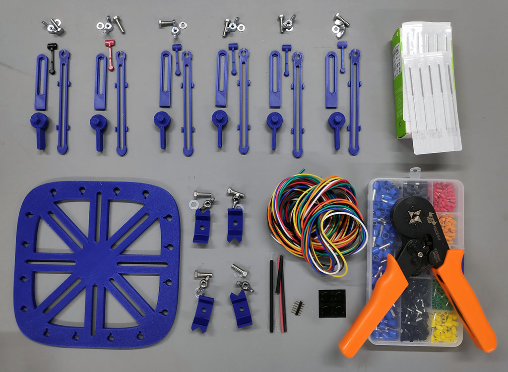
You can print the plastic parts yourself using the files provided on Thingiverse, or you can buy a kit from the designer. I printed the parts over the space of a few days while I was working on other things. The base takes a few hours to print and there are many other parts, so don’t try to rush through it. Collect everything you need and lay it out to make sure you have it all.
Probe arms: 3D-printed parts, M4 bolt with hex head, washer, and M4 wing nut
Pack of acupuncture needles (I used these ones in 0.35x40mm size)
3D-printed base plate
PCB mounts: 3D-printed bracket, M5 bolt with hex head, washer, and M5 wing nut
light-weight, flexible hook-up wire
Pin headers
Heat-shrink tubing (I used 3mm on the pin headers, and 1.5mm on the needles)
The Thingiverse project includes both large and small PCB holders. I’ve only printed the small ones so far. Thread an M5 bolt up through the base and a bracket, and put an M5 washer and wing-nut on top. Make sure the bracket can slide along the slot.
Stick a rubber foot under each corner of the base, to help it sit securely on your bench and give the bolt heads enough clearance to slide without sticking.
Assemble probe brackets
Insert the vertical bracket into the mounting base. I used a drop of superglue to lock it in place.
Danger! If you put superglue into the mounting base and then squeeze in the vertical bracket, the superglue can squirt out under high pressure. Be very careful that you don’t squirt it into your eyes!
The handles of the acupuncture probes that I bought are about 1.3mm in diameter, and didn’t fit into the mounting clips. I drilled out the clips with a 1.5mm drill, and used super-glue to attach them in place with most of the handle sticking out the top.
The mounting clips are a press-fit into the horizontal arm. Use super-glue to fix them permanently.
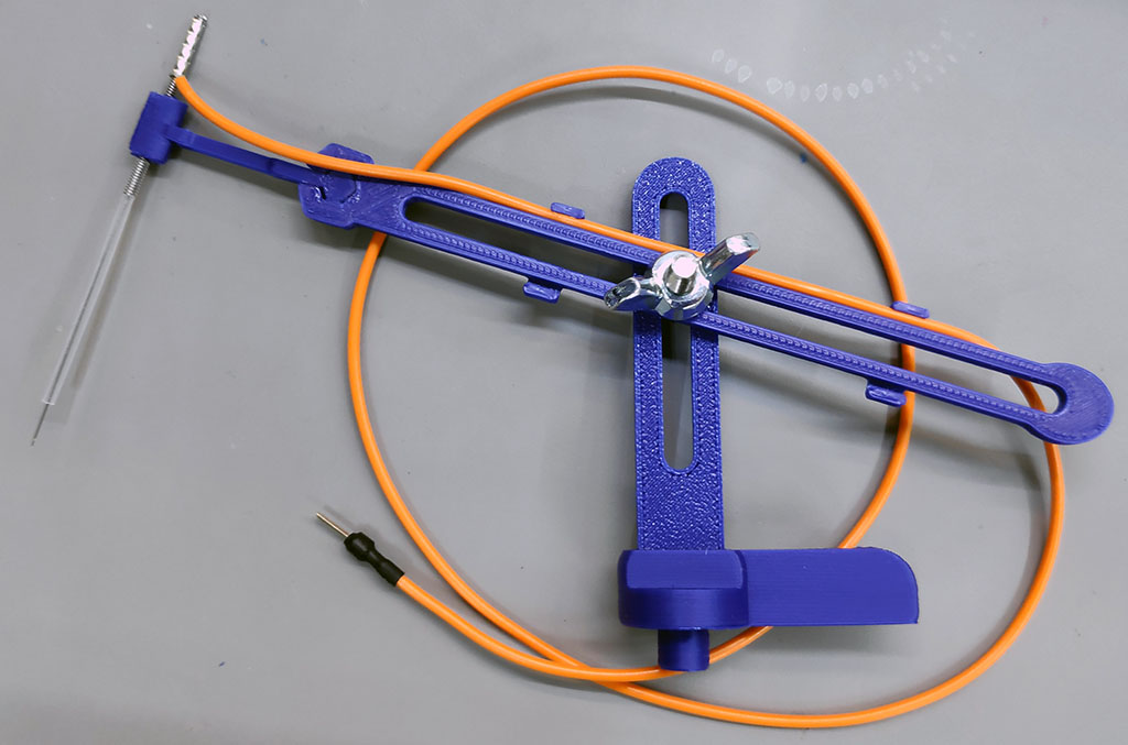
Pass an M4 bolt through the vertical mount and horizontal arm, then put an M4 washer and wing-nut on it.
If the end of the acupuncture needle is plain steel, you can solder the wire directly onto it. My acupuncture needles are all stainless steel so I used a ferrule with the plastic cover removed, and crimped the wire onto the end of the needle.
I put 1.5mm heat-shrink tubing over the needle, with just the end exposed. This is optional but it may help prevent the probes from short-circuiting against each other.
Thread the wire along the horizontal arm. What you put on the other end of the wire is up to you: I soldered on a pin header and then put heat-shrink tubing over the joint. Alternatively, you could put on an alligator clip, a banana plug, a spring clip, or whatever suits you.
Usage
With the device under test mounted on the base, press-fit test probes into the base. Use the handles on the test probes to rotate them, and tighten the wing nut when the needle is in position.
The needles are quite springy, so it’s easy to adjust their position with a pair of tweezers after they are approximately right. The heat-shrink on the needle helps with this, because it’s easy to grip with the tweezers.