Arduino shields are an easy way to quickly test a project or prototype, but they have a big problem. Shields stack up vertically, which isn’t very useful if you want to mount your project inside a box or case, or to make a control panel.
 While working on projects for SuperHouse, I often found that I wanted to mount different parts of the project inside a case so that they could be accessed from the outside. To do that I started using IDC (Insulation Displacement Connector) headers and cables, so that I could link parts together inside the case.
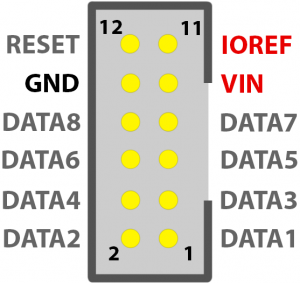
Eventually I settled on a standard pinout for the headers so that I could make interchangable modules or breakouts. The “I/O Breakout” header provides:
- 8 data lines (either analog or digital)
- GND
- IOREF (typically either 3.3V or 5V)
- VIN (the input voltage to the host board)
- RESET (connected to reset on the host board)
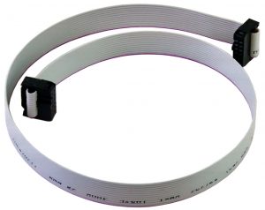
The header is a 12-way, 0.1″ pitch IDC header, which typically uses a shrouded header to ensure that cables can only be plugged in the right way around. The standard header pinout looks like this:
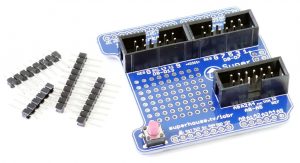
I designed shields for both the regular (Uno-style) and mega Arduino sizes, so that I could simply plug in a shield, plug in an IDC cable, and be ready to go.
The I/O Breakout Shield provides breakouts for sets of I/O lines including A0-A5, D0-D7, and D8-D13 + SCL/SDA:
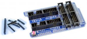
The I/O Breakout Shield Mega provides many more breakouts, for A0-A7, A8-A15, D0-D7, D8-D15, D16-D23, D24-D31, D32-D39, and D40-D47:
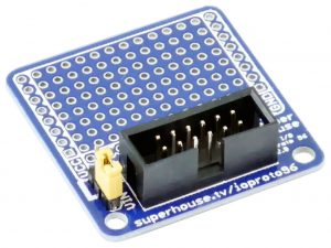
I also designed a variety of modules that can be connected to the shields. The I/O Breakout 96-Point Prototyping Board is a simple prototyping module that provides a general purpose prototyping area with breakouts for the I/O lines:
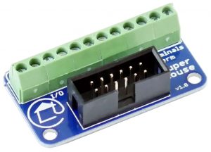
The I/O Breakout Screw Terminals is a very simple converter that provides all the I/O lines as screw terminals for you to connect wires for your project:
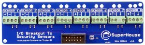
Then we get to the more interesting breakouts! For example, the I/O Breakout To Security Sensors allows you to connect up to 8 security sensors to the analog inputs of your Arduino, so that it can detect things like motion from motion detectors but also detect if the wires have been short-circuited or cut. This is essential for maintaining the integrity of cables to security sensors, and it’s often called “end-of-line” sensing. This breakout also supplies power to the sensors down the cable. By connecting two of these breakouts to the I/O Breakout Mega shield, you can make your own 16-zone security system powered by an Arduino Mega:
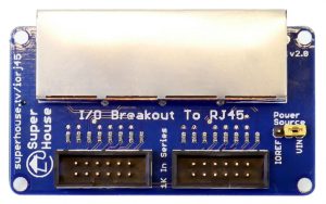
The I/O Breakout To RJ45 provides a set of 4 RJ45 sockets, each of which includes 4 data lines, 2 GND lines, and 2 power lines. The power lines can be linked to either IOREF or VIN of the host Arduino board, and both GND and power use the same pairs as common DIY power over ethernet. I specifically designed this breakout so that I could use Ethernet cables to connect my light switches to my home automation system. It doesn’t actually use Ethernet connections, just the cables, because they’re cheap and easy to make:
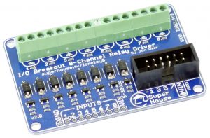
You can control things, too. The I/O Breakout 8 Channel Relay Driver can control up to 8 external relays, which is great for home automation projects. I designed this to control the DIN-rail mounted relays in my switchboards, so that an Arduino can control all the lights in my house. A typical use is to drive relays with 12V coils using either a 3.3V or 5V Arduino:
Over time I’ll probably design more modules using the same I/O breakout headers. I’ve found they’re a great way to quickly assemble a project in the shape that I want it, without being limited by the vertical stack of normal shields.

Hi I have all of my lights and sockets connected back to two metal cabinets containing 20AMP SSR relays mounted on din rails. I’ve also got some 12V din rail transformers to switch the relays. Can the VIN on the relay breakout boards take 12V to switch the relays (I think the relays can take between 3 and 33 volts to switch and probably sink around 30ma. I was hoping to have maybe one or two arduinos per cabinet, with one containing about 34 relays and the other 20 relays. How many of these boards could be powered in this way from one arduino? Also is there any way to manage state change if the arduino restarts. I.e. not turn everything on or off at start up?
Many thanks
Andy
I use Homie in my arduinos for MQTT and house lights.
There’s an option to recovery last state after power failure.
Hi,
Can you please tell me what kind of din rail relays are you using because i’m looking to do the same.
Thanks
Dennis
Hi,
I like your boards, it’s a great idea!
Do you have distributor(s) in Europe for the I/O Breakout Shield? (I didn’t find it on Roboshop).
I would love to have it available in europe also.
Thanks,
Pavel
Are you working on your Breakout for the wallswitches? That one with only one rj45 Breakout?
Can you specify the socket part number you are using? I would like to build a breakout shield for my beaglebone black to work with your breakouts
The socket is a generic part, it could be described as a “0.1 inch pitch 12-way shrouded IDC socket”. I’ve also seen them referred to as a “shrouded box header”. They’re made by so many places that I don’t think there’s a standard part number for them.
i have connected the arduino to 12volt adapter and the vin gives 12volt but when i connect it the 8 channel relay driver in order to control a 12volt din rail relay coil i measure with a polymeter that i get 5volts at the -+ . Can you tell me what am i doing wrong?