My home automation light switches have gone through a series of versions, starting with very complicated switches that all had Ethernet built in. Over time I’ve simplified the system so now the light switches themselves are electrically very simple: they’re just illuminated buttons on a breakout board with an RJ45 connector, and absolutely nothing else in them.
The switches connect to a pair of centralised light switch controllers over Cat-5 cable, so that it can detect when the buttons have been pressed and report events to MQTT.
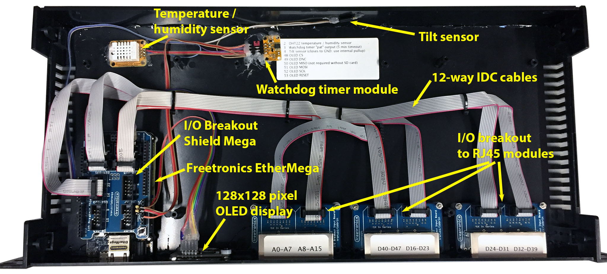
In this episode I show some of the previous versions of my light switches, and then show how I built an Arduino based light switch controller.
Parts used in this project:
- Altronics 1U rack mount case
- Freetronics EtherMega Arduino-compatible with Ethernet
- Freetronics OLED128 display module
- Freetronics Watchdog Timer Module
- Freetronics Temperature / Humidity Sensor Module
- SuperHouse I/O Breakout Shield Mega
- SuperHouse I/O Breakout to RJ45
The source code for the sketch running on the controller is called “LightSwitchControllerMQTT”. You can find it on GitHub at github.com/SuperHouse/LightSwitchControllerMQTT.
There’s also a general introduction to the I/O breakout schema that I use at I/O Breakout. I’ll probably cover this in detail in a future episode because the same breakout shield will be used in other projects.
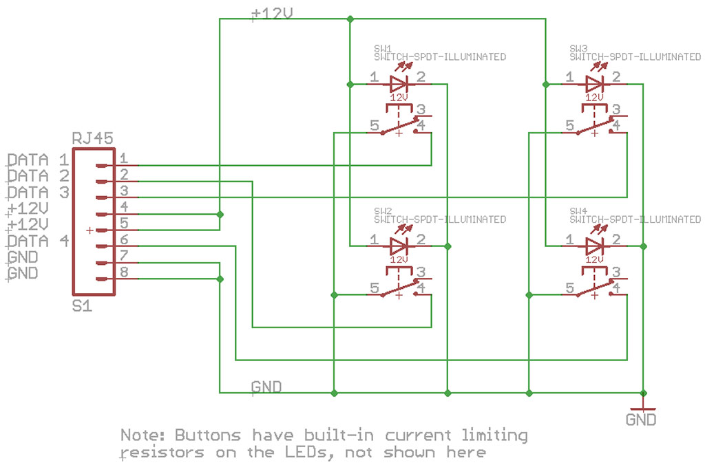
The light switches themselves are just illuminated buttons on a breakout board, mounted on a standard wall plate. The 4-button panel uses all 4 available data lines. The 3 and 2 button panels simply use fewer data lines. Click on the schematic for a larger version:
I didn’t spend much time in this episode explaining the current version of my light switches because I’m going to cover it in much more detail in the future. This episode is mostly about the controller.

I like how you did your controller and im thinking about building one to but i want to know how you did the control at your switch board im getting ready to start building and rewiring my house and wanted to do light controls.
I’ve touched on that in a couple of previous videos, but I’ll be doing an updated one soon.
The overall architecture (which shows how the lighting is wired up) is here: http://www.superhouse.tv/24-home-automation-system-architecture/
Assembly of a switchboard controller. I don’t use this particular controller anymore, but it may be useful background information: http://www.superhouse.tv/12-building-an-arduino-home-automation-controller/
Way back in episode 2 I did an early tour of the switchboard: http://www.superhouse.tv/2-arduino-controlled-home-automation-switchboard/
For retrofitting without doing major recabling, devices like the various Sonoff models are good. I’ll be covering more of these soon: http://staging.superhouse.tv/17-home-automation-control-with-sonoff-arduino-openhab-and-mqtt/ and http://staging.superhouse.tv/21-six-sonoff-secrets/
What kind of controller are you using right now? Im starting to think about house wiring and want to prepare the controller as well. Love your idea of these switches so want to know more information about latest controller. 🙂
I’d really like to thank you for producing such fantastic content. When I first started out on the whole “home automation” journey it seemed like a far fetched dream, but with your guidance and simple to understand explanations I feel confident to venture forth into the relatively unknown. It really is a case of standing on the shoulders of giants, as your explanations are so well presented I now feel confident to not only build my own light controllers, but to add some additional functionality to them (I’m going to add a relay to the 12v circuit so I can turn the LEDs in the light switches on only when the light level drops below X, and turn them off after a certain hour).
Hello,
Why don’t you use the internal hardware watchdog timer inside any Arduino MCU? It needs minimal code, it is pure hardware timer and it may save pins and the watchdog board cost.
I built a similar system, strongly influenced by your inspiration – thanks Jon.
One of the things I found irritating though was the fact that the LED lights in the switches were too bright at night in the bedrooms, so I now power them from a PWM output from the arduino. The sketch subscribes to a topic of “buttons/brightness” and is set by Node Red according to the time of day.
Also I found that switching old flourescent lamps (as still used in my workshop and office) soon developed an annoying habit of welding the relay contacts closed thanks to the inrush current taken by the inductive load, so I now use solid state relays to control these lamps without any problems.
Keep up the good work Jon.
Really interested in how you achieved this, would you be willing to share the code?
Just working on a system with 14 switch panels for the new house.
Andrew
Hi Jonathan
Like this, makes sense to centrally locate the processing. Do you have the parts for this in your shop as a kit?
Hi Jon.
I like this proyect and I have in mind to build my house in this way.
So I have in the cart 2 Ethermega boards, 2 I/O Breakout Mega shields and 6 I/O Breakout to RJ45 (AUD 358.76). I do not know how many switches I will have. The house is in blueprints right now.
What do you know about deliveries to Spain? Some information about taxes, customs,… from another customer from Spain?
Thanks and have a nice Xmas!!
I noticed the Rinnai hot water system controller on the wall. Have you been able to integrate that into your home automation at all?
I would primarily like to be able to monitor the temperature and usage, but setting the temperature when certain conditions are met (like activity in the bathroom to lower the temperature from what it is set for in the kitchen—especially for children).
Hi Jonathan I am Daniel from Nigeria I’ve been following your Videos, I’ll love to build a similar system. Please Email me back to help sale your product here in Nigeria. thanks
What is the break out called that you did not put in for OLED due to vertical space? Thanks, Mathew
Jonathan,
Thanks for this I’d been trying to come up with a non wireless solution for mqtt switches and was hitting a wall. One question though, other than removing the need to wire in a $5 ENC28J60 what’s the benefit of the $120 ethermega vs a standard $20 mega R3?
Great videos Johnathan! Recently purchased my first house and looking to implement a lot of these techniques to make it smart.
The only thing which is missing for me is how have you set up openhab to process these button presses? I have currently got a “Number” item subscribed to the buttons MQTT topic, when this receives an update of the button number, a rule turns a device on or off and resets the Number item to 0.
How have you done yours?
Hi, Jonathan. Could you tell me why you decide not to use optocouplers on digital inputs which uses for buttons.
Only discovered Super House a few days ago as I’m about to move an wanting to get the house automated before we move in, well at least all the cables in.
Just a quick question am I correct in thinking that the system could support 4 breakout boards in total to give me access to 16 switches in all?
Thanks for your willingness to share this stuff.
Andrew
Hi Jonathan,
I am working my way through some home automation, inspired by your projects! So far so good, but I have come across a problem – I need more I/O than it appears an Arduino Mega can provide. I can scrape through with 48 channels, but ideally I would like some capacity in reserve. Can you recommend a method I could adopt and how the code would rearrange? I have seen some people use MUX boards, others link up two Arduinos (in master/slave configuration) but wanted to get your advice.
Your work is great, and thanks for the detailed explanations – they really help!
Regards
Mark
Hi Jonathan
Thanks for your fantastic work. I have built a light switcher, but I am battling with the config and coding of the configuration.yaml and automations.yaml files. I have had 2 very frustrating weeks with minimal progress. Is there any chance you or one of your readers could share the relevant parts of your configuration files.
Doug
I am starting my home automation project off with some Nextion touch panels and some switch plates each with an esp8266 board behind them.
Sonoff 4 channel pro driving 3 speed fan with light.
Sonoff TH16 for fan control in Solar Battery rack.
Sonoff Basic for various other lights in house, garden and fish tanks.
still trying to find a dimmer for LED downlights
Hi Jonathan,
I try to build this light switch controller ordering all parts from your store. I’m afraid about Arduino EtherMega unavailability . It is possible to use Arduino Mega + Ethernet shield with your sketch ?
Hi Jonathan,
How could I modify the processButtonDigital function in order to activate a relay after sensing a the button press event which is in the program? Initial stage I want to make my Home Automation system without MQTT server and want to limit the project for my room only.
thanks in advance
Why did you use a jumper on the watchdog timer, and not a switch on the fromt panel? Now you have to remove the rack and open it up for reprogramming.
Very interesting. Can this this type of switching be used over Can Bus? I have a 38′ boat with a lighting control system using Can Bus between the switch pods and the centralized control unit which activates lighting loads via relays. The bus is four wire with red for 5V power, black for ground and Green and white for Can Low and Can High. I will soon need to replace the switch pods and maybe the control unit, but I don’t want to replace the wiring bus, which is hidden in the finishes of the boat.
hi John,
This project is great. I`ve build the hardware, but it`s giving me hard time to configure.
if I subscribing to : buttons/# . I can see its publishing the “pannel id” – “button id”
I can`t figure out how to subscribe to the individual button or to button state ?
Please help!
Thanks
Andras
Just received the Freetronics OLED128 to use with a Freetronics EtherMega to run the switch controller code. They don’t work together! With the OLED128 enabled the Ethernet port stops working. I have used the latest FTOLED library but still no go. HELP !!
Hi Bill, it sounds like you’ve had the Ethernet and OLED working separately, and it’s only when you try to combine them that it doesn’t work. Is that correct? When you combine them, what code are you running? The example code here is what I’ve been using: https://github.com/SuperHouse/LightSwitchControllerMQTT
Hi Jon,
Thks for your reply.
Can confirm I am using your code as is from Github.
Have tried cut down code with just Ethernet and OLED, but still no go.
Regards Bill.
Hi Jon,
I am using your code exactly as is and Ethernet refuses to work with display plugged in it.
Have been researching trying to find a solution. When it comes to SPI bus clock timing, rising vs falling, etc.. but it all goes over my head and am now stuck.
Cheers, Bill
It appears I have found a solution. Using an external power supply rather than USB fixes this problem.
Regards, Bill
Hi Jon,
Firstly, love the content. Been a long time patrion. I have built one of these and am having some issues getting it to connect to my home assistant mosquito. I am trying to work out how to add authentication to the connection. New to arduino coding, so bear with me please.
I think that clientBuffer contains clientString which is basically
Reconnecting Arduino- 192.168.xxx.xxx
so
client.connect(“Reconnecting Arduino- 192.168.xxx.xxx”)
but in the pubsubclient documentation is the below connection command, so im just wondering how i add this to the connection request?
client.connect(“arduinoClient”, “testuser”, “testpass”)
or am i totally wrong????
// Attempt to connect
String clientString = “Reconnecting Arduino-” + String(Ethernet.localIP());
clientString.toCharArray(clientBuffer, clientString.length()+1);
if (client.connect(clientBuffer)) {
Serial.println(“connected”);
// Once connected, publish an announcement…
clientString.toCharArray(clientBuffer, clientString.length() + 1);
client.publish(statusTopic, clientBuffer);
// … and resubscribe
//client.subscribe(“inTopic”);
Hey John, thanks for your support!
I’m looking at my code now, and it doesn’t make sense to me either. Current me wonders what past me was thinking. The way you’re calling it looks correct, with the username and password as the 2nd and 3rd arguments.
I think I messed up the first argument, because it’s using the entire string including the “Reconnecting ” prefix. That doesn’t look right. You could try just putting a simple unique ID there to see if it connects.
Thanks for your reply, I did get it connecting to mosquito last night, now im just trying to work out how to create switches and sensors.
I just replaced this line client.connect(clientBuffer) with client.connect(“clientid”,”username”,”password”) and all started working.
I can see the data eg the buttons, events, temperature and humidity readings on the mqtt broker topics in node red and with 3rd party mqtt clients, but home assistant cant see it. I created an mqtt sensor below, but get no data..
sensor:
– platform: mqtt
name: “Temperature”
state_topic: “lightswitcheast/temperature”
unit_of_measurement: ‘°C’
value_template: “{{ value_json.temperature }}”
– platform: mqtt
name: “Humidity”
state_topic: “lightswitcheast/humidity”
unit_of_measurement: ‘%’
value_template: “{{ value_json.humidity }}”
And have no idea yet how to create switches in HA for each button?
Love your work thou, ive watched a lot of channels on home automation and yours have been the best most comprehensive, and i just like the way you do things. Anyways keep up the good work, we know its hard to create content all the time, we all have a life… Would love to see some content on home assistant and node red and connecting this light switch controller to HA using node red would be awesome.
I got the Temperature and Humidity working just had to remove the value.template line. Still have no idea on how to get a button to turn on say toggle switch.sonoff for example?
worked it out..
automation:
trigger:
platform: mqtt
topic: buttons
payload: “20-58” #switch number
encoding: “utf-8”
action:
service: switch.toggle
entity_id: switch.sonoff
What an Awesome project, i am am an electrician in the uk and i completely agree with hard wiring switches, i will be making an Arduino centralised switch board like yours.
i have a question about dimming my ac led lights, i can use the switches to connect to mqtt and node red to initiate the sequence of turning on the lights but i cant find a solution to dimmable light controller which i can trigger with a logic input, the only ways ive seen are via wifi… could you help if you know of any way to dim lights with a wired connection.
Thanks so much for your work