Modules
Showing 1–12 of 15 results
-
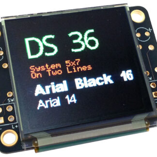
128×128 Pixel OLED Module
$58.00 Read more -
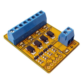
4-Channel Relay Driver Module
$8.00 Read more -
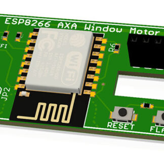
AXA Remote WiFi Interface
$30.00 Read more -
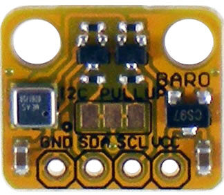
Barometric Pressure Sensor Module
$19.00 Add to cart -
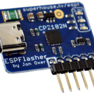
ESPFlasher ESP8266 / ESP32 USB serial flasher
$16.00 Read more -
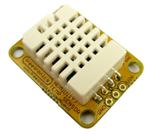
Humidity and Temperature Sensor Module
$22.00 Add to cart -
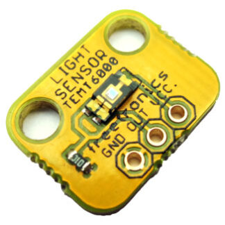
Light Sensor Module
$5.00 Add to cart -
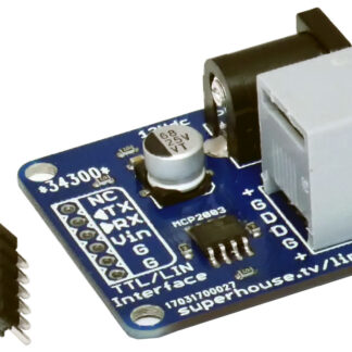
LIN bus serial adapter module
$14.00 Add to cart -
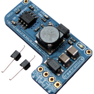
Power Regulator 28V for PoE and Project Powering
$10.00 Add to cart -
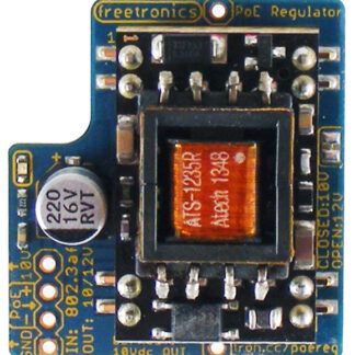
Power-over-Ethernet Regulator 802.3af
$29.00 Add to cart -
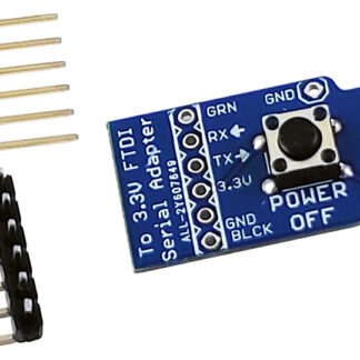
Sonoff Programming Adapter
$5.00 Read more -
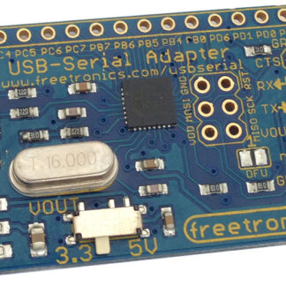
USB Serial Adapter
$19.00 Read more
Showing 1–12 of 15 results